Bytecode and the Busicom
The innovative use of a virtual machine helps explain the quirks of the 4004
We’ve covered the architecture of the 4004 and its oddities. We’re now going to look at how that architecture was used to implement the Busicom 141-PF calculator. There are a few surprises along the way including one innovation that has often been overlooked.
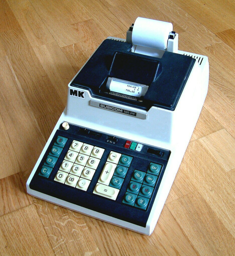
We need to say a few things about the 141-PF first though. It was quite a rudimentary calculator by today’s standards. There was no electronic display and all results were printed on a paper roll. It worked with fixed point numbers. A sliding selector on the keyboard indicated how many digits after the decimal point would be used.
Typical use of the 141-PF would be to add lots of accounting entries. The paper roll would provide an elementary ‘audit trail’ and allow someone to check that the numbers had been entered correctly.
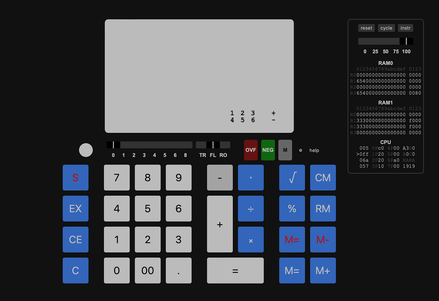
There is a nice emulator of 141-PF online at https://dutchen18.gitlab.io/emu-rs/ that demonstrates how all this worked. The results are not always what you might expect!
Inside the 141-PF
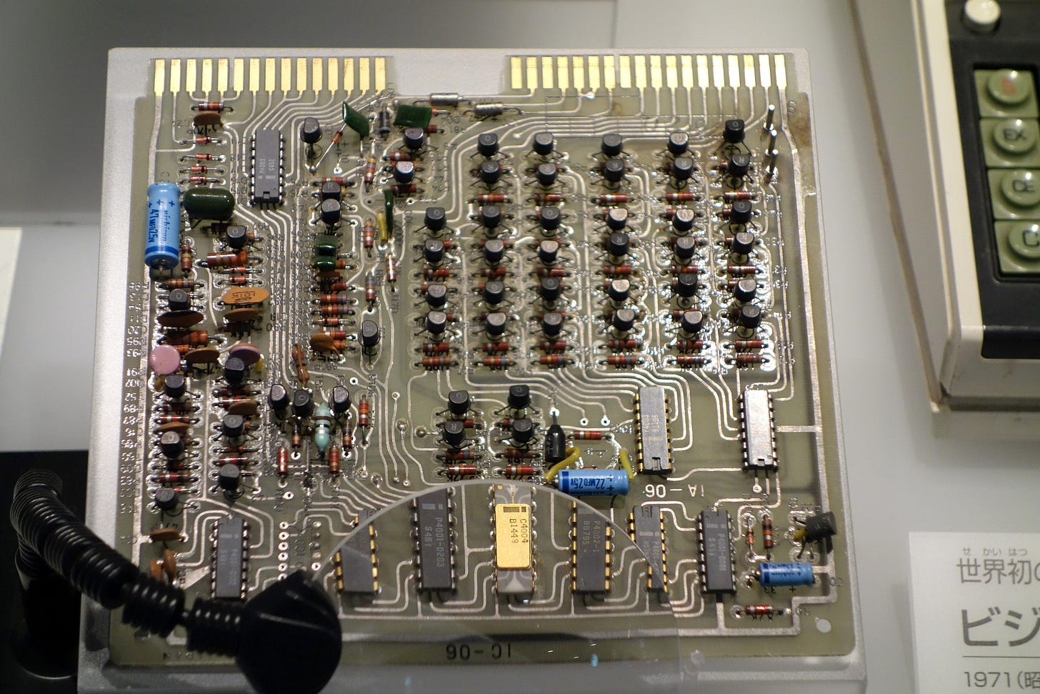
The calculator was implemented using a 4004, four 4001 256-byte ROM chips, two 4002 80-nibble RAM chips and a single 4003 shift register.
An optional additional ROM chip allowed the calculation of square roots.
The Calculator Program
For the 35th anniversary of the 4004, a fantastic piece of work to recover and disassemble the 141-PF’s ROM chips was undertaken. The result of this is available here. It’s a great piece of work, with extensive annotations and explanations.
The major surprise is that the 1K of ROM memory implements a simple ‘virtual machine’. This machine in turn performs the arithmetic and other calculations needed by the 141-PF.
This virtual machine implements a completely different instruction set which operates on a number of ‘registers’ held in the 141-PF’s RAM.
With this knowledge, we can start to understand some of the oddities of the 4004.
First of all, this explains the presence of the JIN (“Jump Indirect”) instruction that replaces the last eight bits of the program counter with an index register pair. This instruction is key in enabling the 4004 to run the code associated with a given virtual machine instruction.
The virtual machine instruction opcode (a single byte) is the address in the second (256-byte) page of the 4004’s memory where the 4004 code to implement that instruction is located. The 4004 simply loads the opcode into an index register pair and performs a ‘JIN’ instruction.
This allowed helps us to understand the strange RAM structure which we saw earlier in the 4004 assembly language manual.
The labelling here of a row as a ‘DATA RAM REGISTER’ now makes sense. Each ‘row’ of RAM corresponds to a register in the virtual machine. Each register holds a single fixed point number. The four status characters associated with each row contain information relevant to that number, such as the position of the decimal point.
The eight sets of 20 nibbles of memory in the 141-PF thus (with one exception) correspond to fixed point numbers. The disassembly helpfully summarises the register use as follows:
KR corresponds to the keyboard buffer rather than a number.
We can see how these numbers are stored in the RAM by activating the memory display in the emulator. As seen top right below, it’s activated by pressing the circle next to the ‘help’ button.
So to give just one example of virtual machine instructions we have:
MOV RR,WRWhich moves the working register into the result register.
In slightly simplified terms the ROM is used as follows.
There are a total of 88 virtual machine instructions. This means that the implementation of all 88 instructions has been squeezed into 512 bytes!
Explaining the 4004
So we’ve now found some more explanations for some of the odd features of the 4004: they were there to support the implementation of the 141-PF’s virtual machine.
The use of a virtual machine was, in part, because of a lack of memory space, as space is very tight in the 141-PF’s ROMs. One byte of a virtual machine instruction would take up less space than a 4004 subroutine call.
It could also have been because the 4004 team started with the original Busicom design that had more specialised instructions and then converted these instructions into the more rudimentary 4004 instructions.
This is consistent with the account given by Shima. He talks about ‘n-digit macroinstructions’ in the original Busicom design. He also explains the existence of the ‘JIN’ jump indirect instruction.
To utilize a subroutine, you always have to use two bytes. Here I showed the total number of steps for calculators was roughly 200 steps. I did not want to add an extra ROM chip, I wanted to use only 200 bytes instead of 400 bytes. Then I asked to add the register indirect addressing mode, which solved my problem.
Also, this added register indirect jump instruction was able to solve the fourth problem altogether. With its register indirect jump instruction, the interpret routine was developed for the emulation of the desktop calculator’s macroinstruction.
It’s impressive that they managed to squeeze a virtual machine with 88 instructions, code to control the keyboard and printer, and the calculator code itself into 1K.
So finally, the 4004 instruction set makes sense. Here’s the scenario. Intel and Ted Hoff initially had one customer, Busicom. They had to convince Busicom management that they were building a processor that would be cost-effective for Busicom’s needs. That meant special features to support implementation of Shima’s code. It also meant leaving out anything that was superfluous.
One could say that one aspect of the genius of the 4004 design was making a design for a calculator just powerful enough to make it more widely useful.
And we mustn’t overlook the novelty of the idea of using a virtual machine. Quoting Shima again Hoff came to him with the idea of converting macroinstructions into 4004 code:
His basic idea was that rather than implementing a programmable n-digit macroinstructions, let us make your macro-instructions by simple one-digit instructions using a program. This one digit meant four bits. I thought that looked good.
It then seems to have been Shima who suggested that calls to 4004 subroutines be replaced by the more compact single byte representation.
According to my research, the first use of ‘byte code’ in this way was in around 1966 in the BCPL programming language. So this wasn't a completely novel idea. There is no evidence that either Hoff or Shima was aware of earlier implementations, though, and its use in this context does seem to have been genuinely new.
The Significance Of The 4004
The 4004 architecture, with all its quirks, did its job. Intel did convince Busicom management to use Hoff’s idea. The 4004 was successfully implemented by Federico Faggin and his team. The 4004 was successfully used in other products.
And of course, the 4004 was the start of Intel’s lucrative microprocessor business. But Intel would need to look elsewhere for a design to take that business into its next stage of development. The story of that design will be the subject of a future post.
Photo Credits
Christian Bassow
CC BY-SA 4.0 <https://creativecommons.org/licenses/by-sa/4.0>
via Wikimedia Commons


