Inmos and the Transputer : Instruction Set and Architecture
A more detailed look at the Transputer

In Inmos and the Transputer - Part 1 : Parallel Ventures we looked at the early history of Inmos and had our first look at the Transputer. In this supplementary post we’re going to look in much more detail at the Transputer Instruction Set and Architecture.
Let’s find out more about the design and what made the Transputer’s architecture radically different from the ‘classic’ RISC designs of the era that we’ve already discussed. As we’ll see there are quite a few surprises in the design.

Transputer Series
We saw in ‘Inmos and the Transputer : Part 1’, there were three main series of Transputers that made it to production: T2, T4 and T8.
T2: The initial prototype Transputer was the T212 a 16-bit design that lacked scheduling hardware.
T4: The T414 appeared in October 1985 and was a 32-bit design with 4k of onboard memory.
T8:The T800 transputer was introduced in 1987 added a 64-bit floating-point unit (FPU) and registers for floating point.
We’re going to look at the 32-bit T800 series in this post. All registers are 32-bit wide and addresses are 32-bits long.
Registers
Let’s start with the Transputer’s registers. The Transputer had only six registers. From the Transputer Databook:
The design of the transputer processor exploits the availability of fast on-chip memory by having only a small number of registers; the CPU contains six registers which are used in the execution of a sequential process. The small number of registers, together with the simplicity of the instruction set enables the processor to have relatively simple (and fast) data-paths and control logic.
The six registers are:
The workspace pointer which points to an area of store where local variables are kept.
The instruction pointer which points to the next instruction to be executed.
The operand register which is used in the formation of instruction operands.
The A, B and C registers which form an evaluation stack, and are the sources and destinations for most arithmetic and logical operations. Loading a value into the stack pushes B into C, and A into B, before loading A. Storing a value from A, pops B into A and C into B.
So the the Transputer was a stack machine, but one with a very small (3 element) stack.
Expressions are evaluated on the evaluation stack, and instructions refer to the stack implicitly. For example, the add instruction adds the top two values in the stack and places the result on the top of the stack. The use of a stack removes the need for instructions to respecify the location of their operands. Statistics gathered from a large number of programs show that three registers provide an effective balance between code compactness and implementation complexity.
This is all very different to the design of the early RISC processors of the 1980s which typically had a large number of general purpose registers (32 for each of RISC 1, MIPS and ARM). RISC instructions would typically allow operations to take place on any of the general purpose registers.
Why was this? The use of a small number of registers and a small stack in this way makes sense when one considers that the Transputer was designed for parallel processing. A key requirement was that it should support very fast switching between processes. A small number of registers could be saved much more quickly than the large number of registers on a typical RISC design.
Instruction Set
Let’s now look at the Transputer’s instruction set. From the Transputer Databook:
It was a design decision that the transputer should be programmed in a high-level language. The instruction set has, therefore, been designed for simple and efficient compilation. It contains a relatively small number of instructions, all with the same format, chosen to give a compact representation of the operations most frequently occuring in programs.
This sounds very much like a RISC design, but …
Each instruction consists of a single byte divided into two 4-bit parts. The four most significant bits of the byte are a function code, and the four least significant bits are a data value.
This doesn’t sound too much like the classic RISC designs of the 1980s which typically had 32-bit or perhaps 16-bit instruction lengths. How did the Transputer manage to encode its instructions into just eight bits?
The basic instruction format breaks that byte into two 4-bit ‘nibbles’. The upper nibble specifies one of 16 ‘operations’ or ‘functions’ as the Transputer documentation calls them. The lower 4 bits specifies a small integer constant.
This format allows loading of small integer values:
The load constant instruction enables values between 0 and 15 to be loaded with a single byte instruction.
and loading of values close to a ‘workspace pointer’:
The load local and store local instructions access locations in memory relative to the workspace pointer. The first 16 locations can be accessed using a single byte instruction.
Other instructions that are encoded into a single byte include jump, call and add constant. There are 13 instructions (out of a possible 16) that are encoded in this way.
Two of the remaining 16 possible operations are reserved as ‘prefix’ functions. Let’s explain what prefix instructions do.
All instructions are executed by loading the four data bits into the least significant four bits of the operand register, which is then used as the the instruction's operand. All instructions except the prefix instructions end by clearing the operand register, ready for the next instruction.
The naming of the ‘operand’ register is a little confusing, as it actually fulfils multiple roles. All will become clear in a few paragraphs.
Multiple prefix instructions can be combined together to generate 12 bit, 16 bit and so on values in the operand register.
Consequently operands can be extended to any length up to the length of the operand register by a sequence of prefix instructions.
But what about other instructions that we need to complete the instruction set?
We still have left one of the available 16 operations that can be encoded in the upper nibble of the instruction byte. This operation is known in the Inmos documentation as ‘operate’. This interprets the value in the operand register as an instruction code. With the use of prefix instructions this code can be extended to 8, 12, 16 and so on number of bits.
So we now have three classes of instruction.
Encoded into a single byte with a 4-bit operand in the instruction.
Encoded into a single byte with no operand encoded into the instruction.
Treats the value in the operand register as an instruction code.
Let’s give an example of the third type of instruction.
The operation ‘ladd’ for ‘long add’ is encoded as #21F6.
The first byte #21 places 1 into the operand register. The second byte #F6 shifts that by 4 bits and adds 6 giving #16 which is the ‘opcode’ for ‘ladd’.
This elaborate encoding was to try to make Transputer code as compact as possible:
Measurements show that about 70% of executed instructions are encoded in a single byte (ie without the use of prefix instructions). Many of these instructions, such as load constant and add require just one processor cycle.
We can see that this is radically different to the approach typically used in RISC designs of the era which would use 32-bit or 16-bit instructions.
Why take this approach? The Transputer had a very small amount (a few kbytes) of on-board memory, so it was vitally important to squeeze as much code into that memory as possible. The 32-bit or 16-bit instruction lengths of RISC designs would have just been too big.
Microcode
If the instruction set, or at least the encoding, is very different to classic RISC architectures, the the implementation was very different too. It made extensive use of microcode, which was generally avoided by mainstream RISC implementations.
This microcode based implementation still allowed for fast execution of many instructions. Of the single byte instructions that INMOS indicated made upon 70% of executed instructions, the majority could be executed in a single clock cycle.
According to David May, the Transputer’s microcode was formally verified:
The microcode was formally verified by using an Occam program transformation system to transform the microcode (represented in Occam) into a high-level program that had already been verified. This was a very early use of formal methods in microprocessor design.
The microcode itself for a range of Transputers is actually available for download from transputer.net. Here is a short sample of the 122-bit long microcode for the T800.
May has also provided some original documentation on the development of the Transputer, including the development and verification of its microcode.
Floating Point
Some versions of the Transputer (for example the T800) implement floating point arithmetic using a shallow stack with an approach similar to the one we’ve described above. Transputer architect, David May, has said:
The T800 was a very early implementation of the IEEE 754 standard. At the time of introduction, it was the fastest floating point microcomputer in the world.
On-Board Memory
The T800 series had 4k of onboard Random Access Memory which was mapped to memory address #80000000. Onboard memory could contain either programs or data and could be accessed in a single cycle. For comparison, external memory access needed three or more cycles.
Inside the Transputer
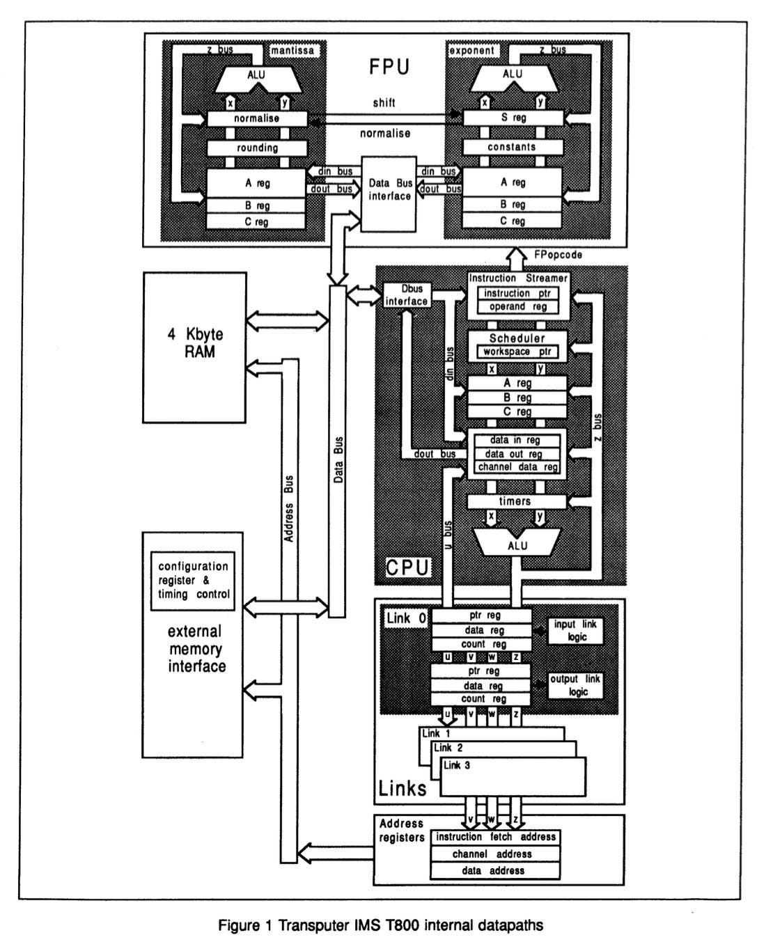
Bringing this all together, the Transputer Databook has a helpful picture of the T800’s internal datapaths, which shows how each of these elements were linked together.
Summary
We’ve discovered why the Transputer doesn’t belong with the RISC architectures of the 1980s. It follows a very different design philosophy.
The Transputer might even be described as a high-speed microcontroller. It was designed to be effective as a stand-alone device using a few kbytes of onboard memory. As such it had to try to achieve very high code density. It did so with a fairly elaborate instruction encoding.
The existence of this fast RAM on the Transputer reduced the need for large numbers of registers.
The fullest description of the Transputer instruction set is given in the ‘Transputer Instruction Set Manual’ that can be downloaded from transputer.net. Click on the image of the book of here to download a pdf version of the book.
Transputers In Action : ‘Parallel Processing Unparalleled Potential’
We’re going to end with a demonstration of the Transputer in action, in the form of an Inmos promotional film from the early 1990s. We’ll find out what happened to the Transputer in the next post in this short series.
Thanks so much for supporting ‘The Chip Letter’.


Wow I never heard of this, but this is a fascinating design for a microprocessor!